Release V2
In the UK, half a million shopping trolleys are abandoned annually. Costing British businesses £35m, Release fixes that.
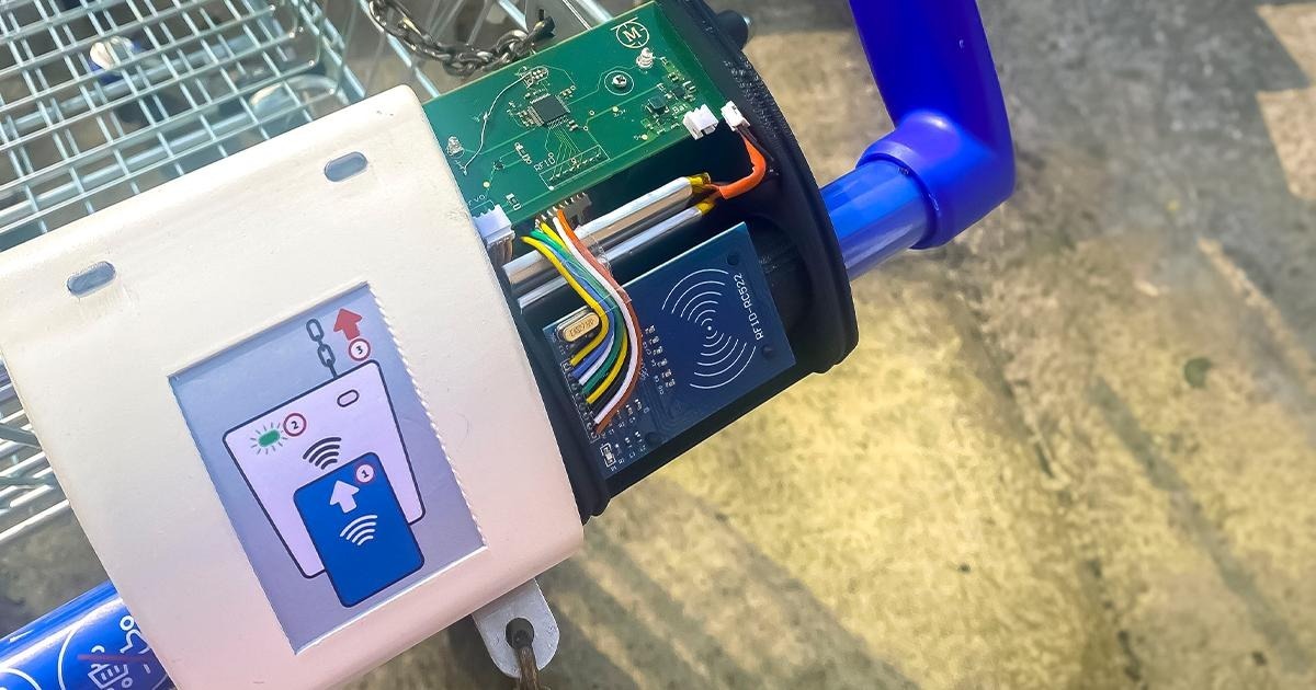
Release the Electronic Trolley Lock for supermarkets
Overview
- In the UK, over half a million shopping trolleys are abandoned annually.
- It costs British businesses £35m a year, and that doesnt include environmental damages!
- Here is the engineering development to get to the finished prototype.
Methodology
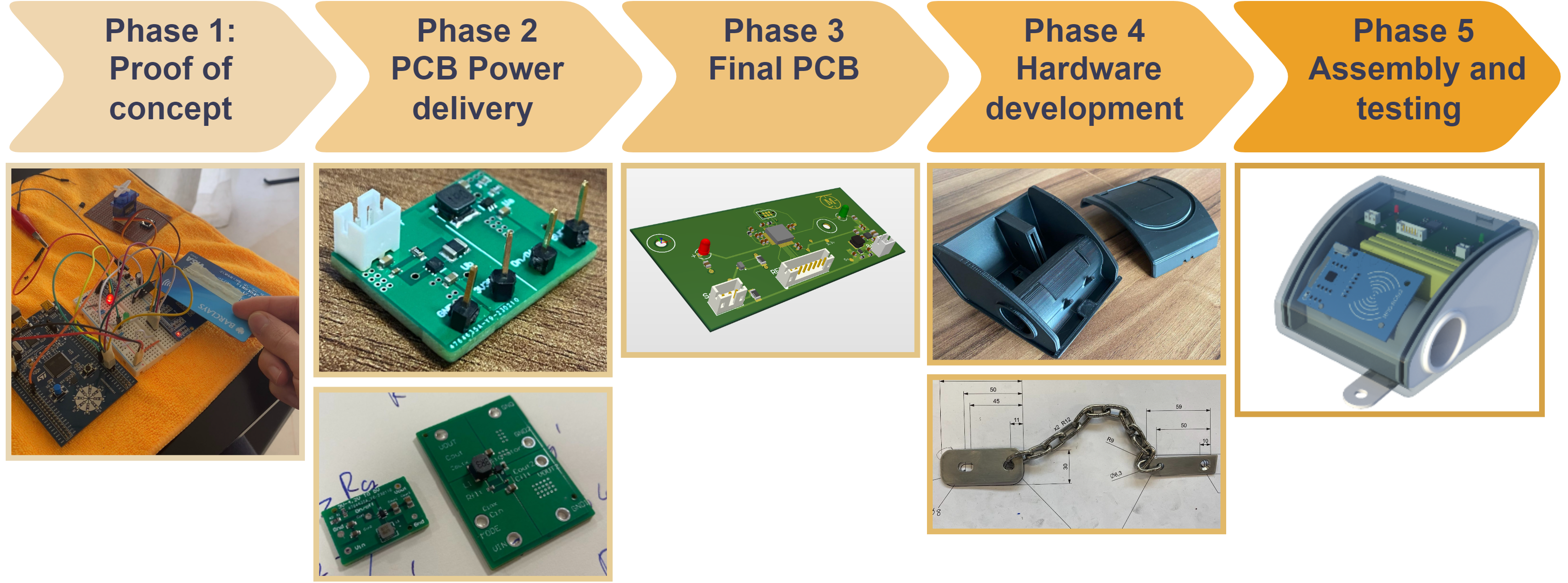
Altium PCB Design
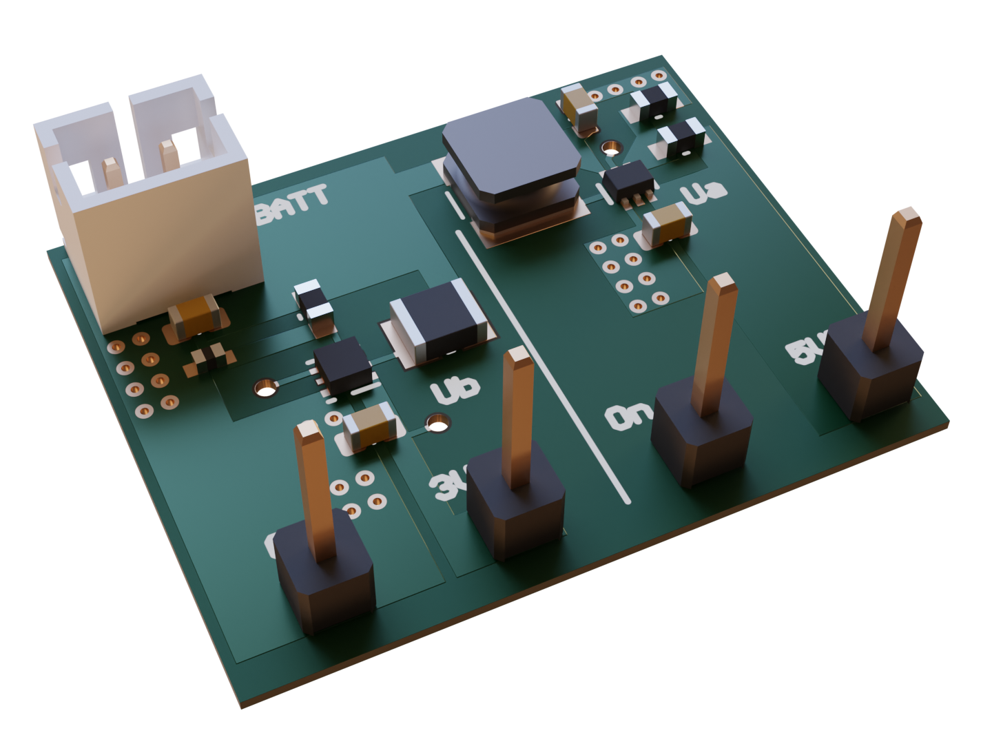
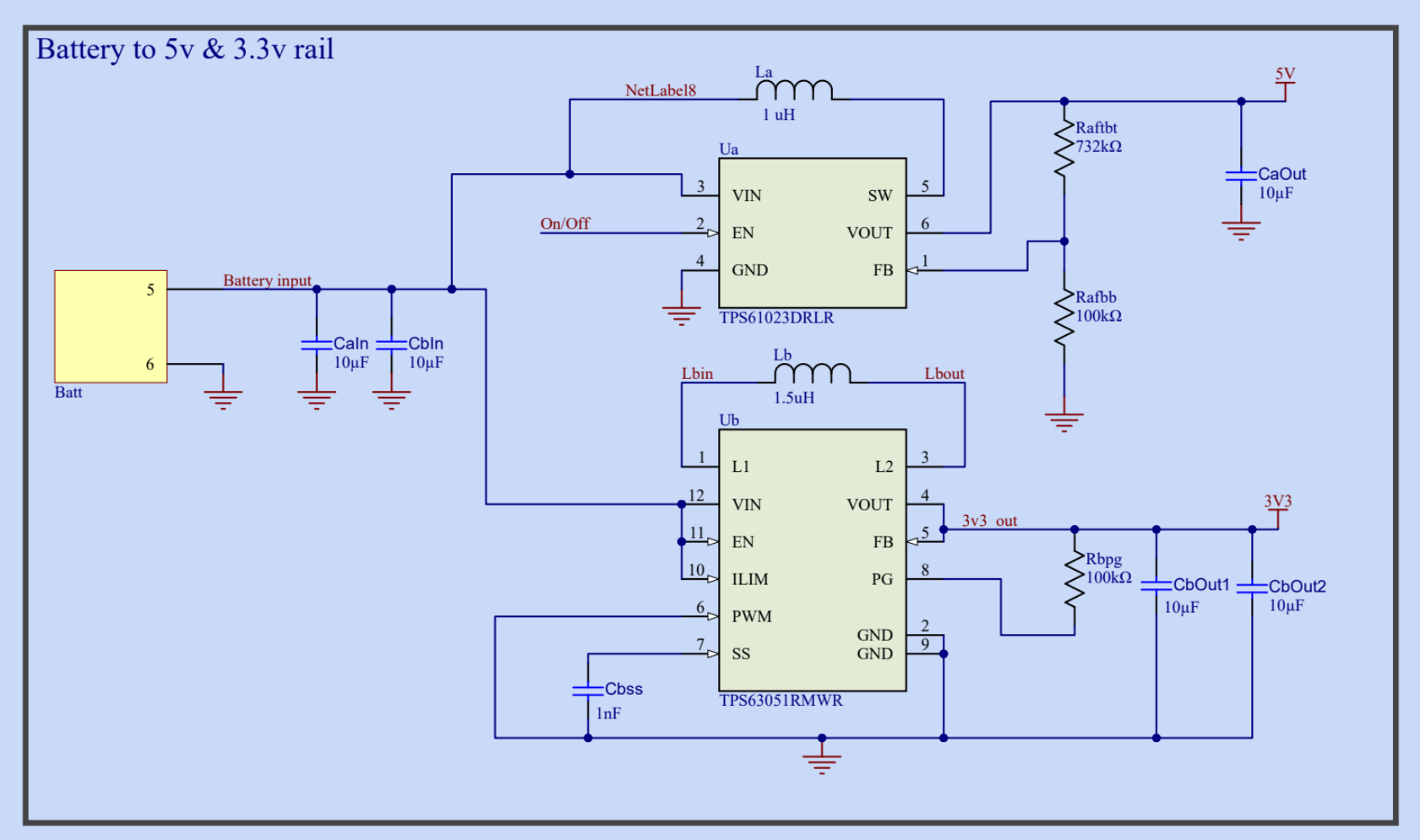
DC to DC power supply
A power supply board was made to test TI DC to DC converters chips for my power requirements. I designed a dev board with two power rails, a 3.3v 200mA high effeciency rail and a higher power 5v 1A for the servo.
- 5v rail
- TPS61023
- Boost converter
- 3.3v rail
This was a lovely development for introduction to DC-DC converters and to distinguish buck from boost converters
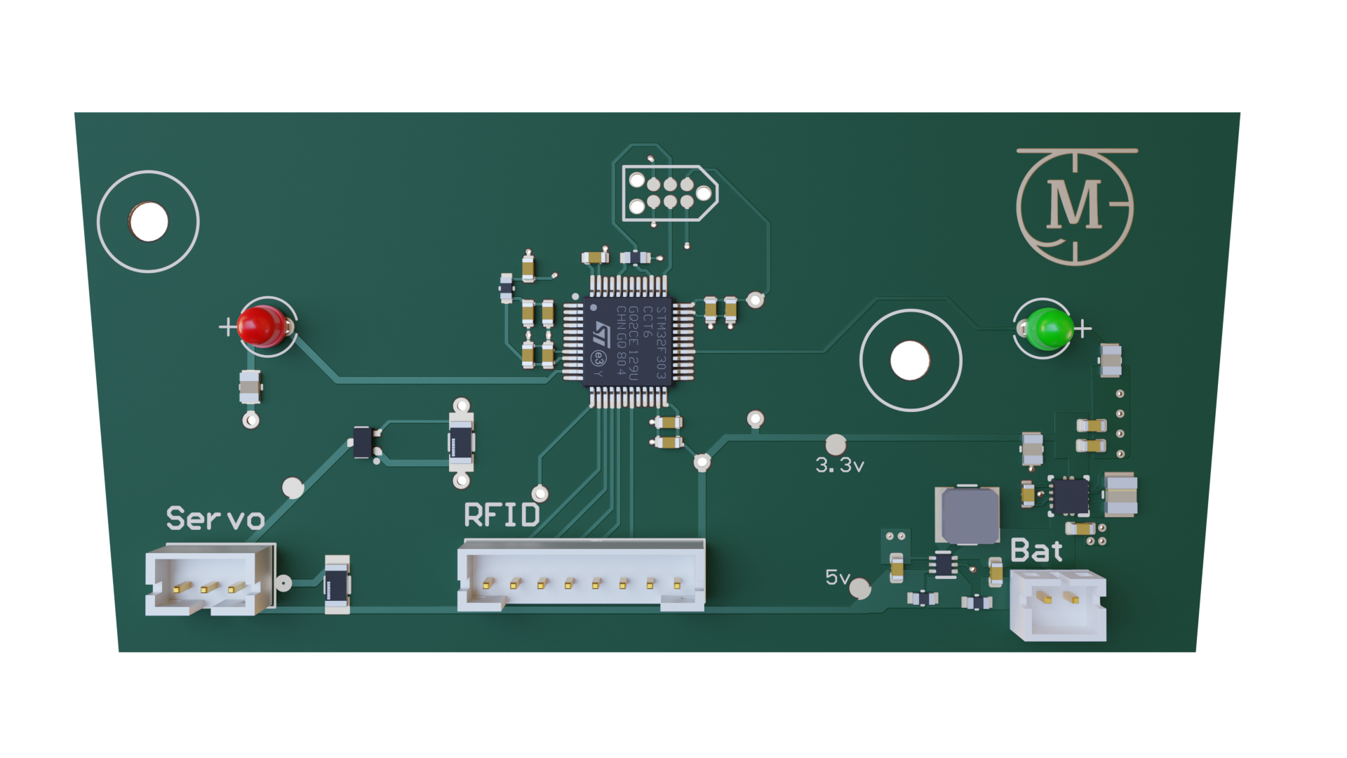
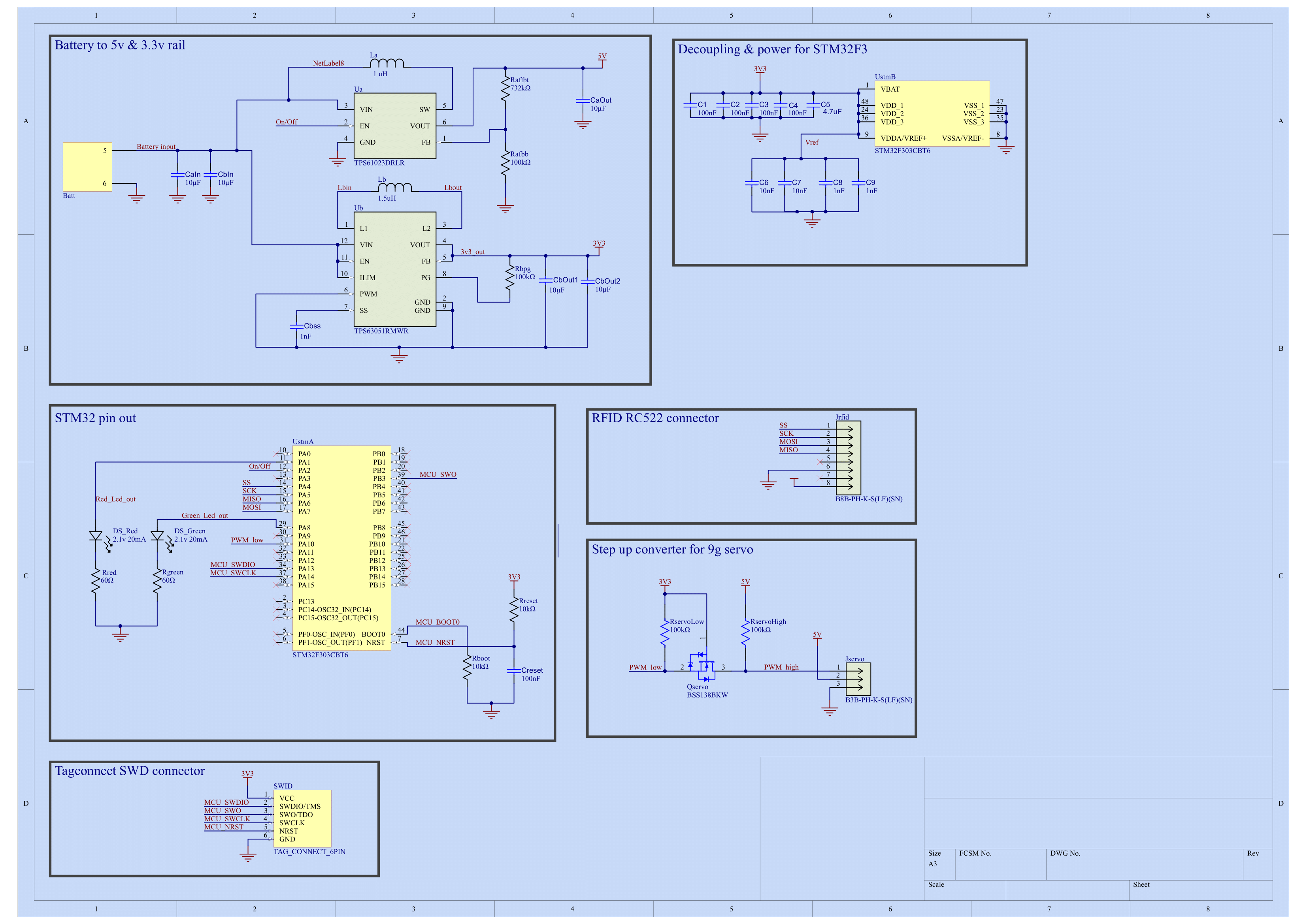
Main PCB
Here I joined the previous power supply work while including the mcu and pereferals.
- STM32F4
- Embedded rust
- DC-DC converter design
- LED design choices
- Logic Level Converter
- Tag SWG connector
- Manufacturing considerations
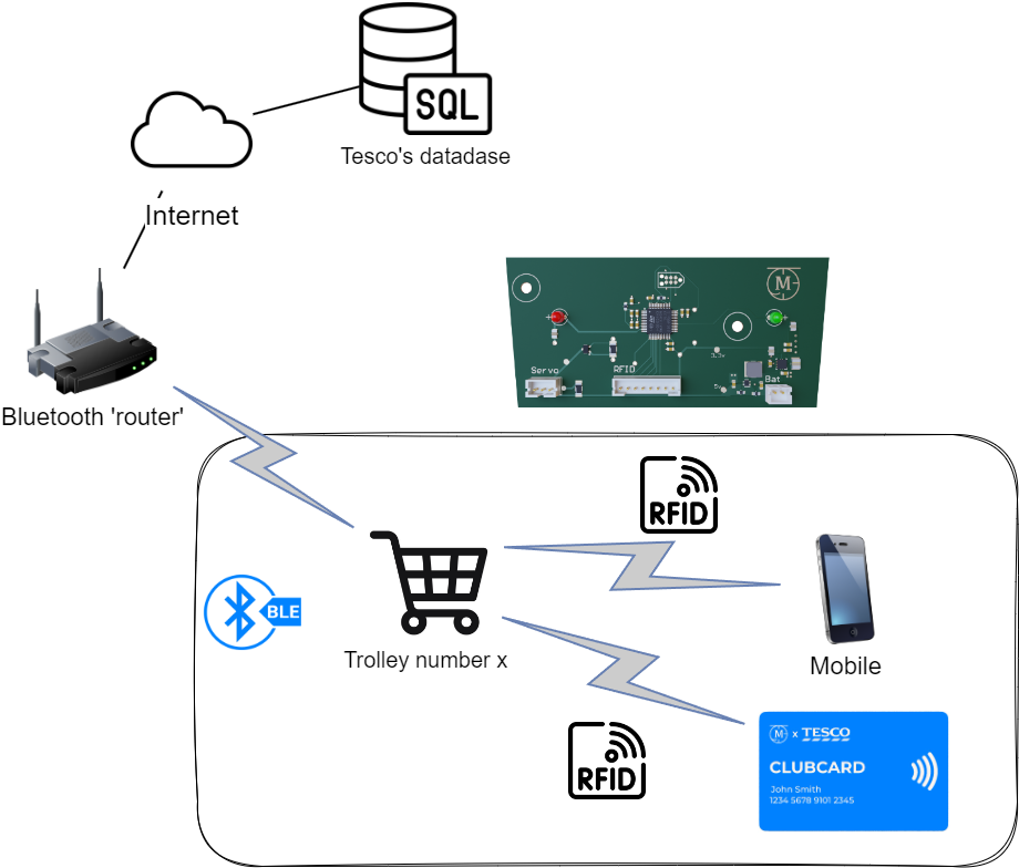
IoT Functionality
- Explain how the IoT system integrates with the hardware.
- Mention key features and benefits, such as remote control and monitoring.
Code & Firmware
Why did you choose rust instead of C?
Good question, I chose rust for the following reasons.
- Safety. It basically meant that it was extremely hard for me to introduce memory safety bugs, even with my lack of embedded experience!
- Rust is a new language compared to C. It let me personally find out what all the fuss is about.
- Rust is backed by a great community. Meaning help was only a few tickets away.
- Most importantly A driver for the RFID reader I was using already existed MFRC522,
- Hierarchical directory structure for embedded rust
1
2
3
4
5
6
7
8
9
10
11
12
13
14
15
16
17
18
19
20
21
22
23
24
25
26
27
28
29
30
31
32
33
34
35
36
37
38
39
40
41
42
43
44
#![no_std]
#![no_main]

use defmt_rtt as _;
use panic_probe as _;
use stm32f3xx_hal as hal;

use mfrc522::{Mfrc522, Uid};

#[cortex_m_rt::entry]
fn main() -> ! {
    // Initialization code for peripherals and configuration

    // List of cards with access
    let uid_card_pass_1 = [74, 152, 138, 25];

    // Peripheral initialization and clock configuration

    // SPI configuration for MFRC522

    // Main loop for RFID card detection and handling

    // Loop for locking and unlocking

    loop {
        // Main loop content
    }
}

// Function for handling RFID card operations
fn handle_card<E, SPI, NSS>(mfrc522: &mut Mfrc522<SPI, NSS>, uid: &Uid, write: bool)
where
    SPI: spi::Transfer<u8, Error = E> + spi::Write<u8, Error = E>,
    NSS: OutputPin,
{
    // RFID card authentication and read/write operations
}

// Panic handler and application termination function
#[defmt::panic_handler]
fn panic() -> ! {
    cortex_m::asm::udf()
}
Hardware development Phase 4.
Locking Mechanism
For the trolley to be locked and unlocked, I needed to design a mechanism that could be controlled by a microcontroller instead of a 1£ coin. Initial concept was a Slider crank mechanism where we convert the rotational displace from a servo to a forward displacement to push a pin into the key.
Slider crank mechanism required 3 joins, which would wear down overtime and require lubrication. For a mass produced product, this is not idea.
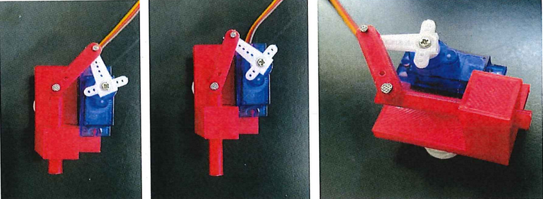
Compliant Mechanism
Exploring compliant mechanisms became the logical next step, especially with the accessibility of a 3D printer, aiming to overcome the setbacks encountered with the slider crank mechanism. The iterative process is vividly captured in the following table:
Mech Pin Iterations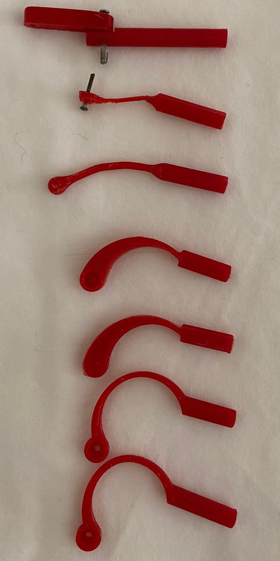 | Mech Case Iterations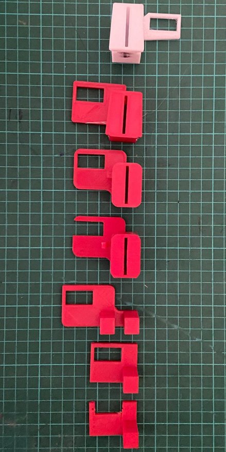 |
Comparison of O-Ring and Gasket Designs
- The intended solution from ReleaseV1 was to split the case at the seam to hide the split lines.
- Due to all the organic angles and corves this made designing the gasket complicated
Solution: O-ring Design!
| O-Ring Design | Gasket Design |
|---|---|
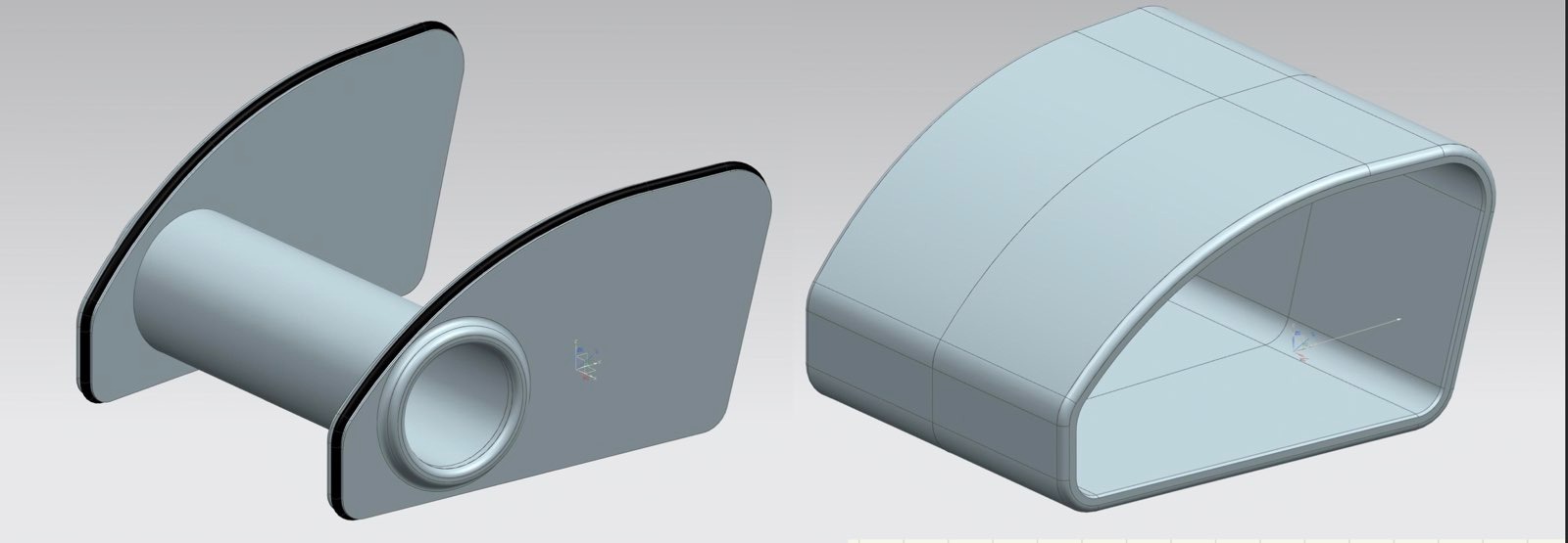 | 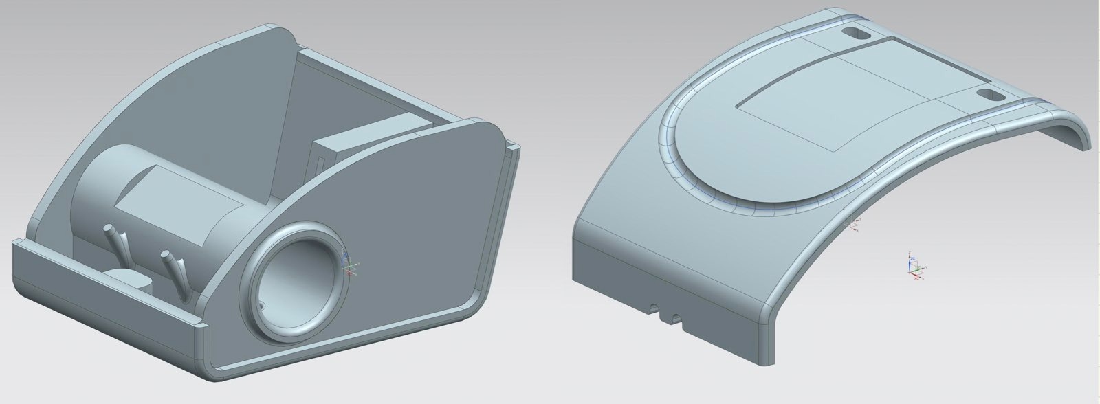 |
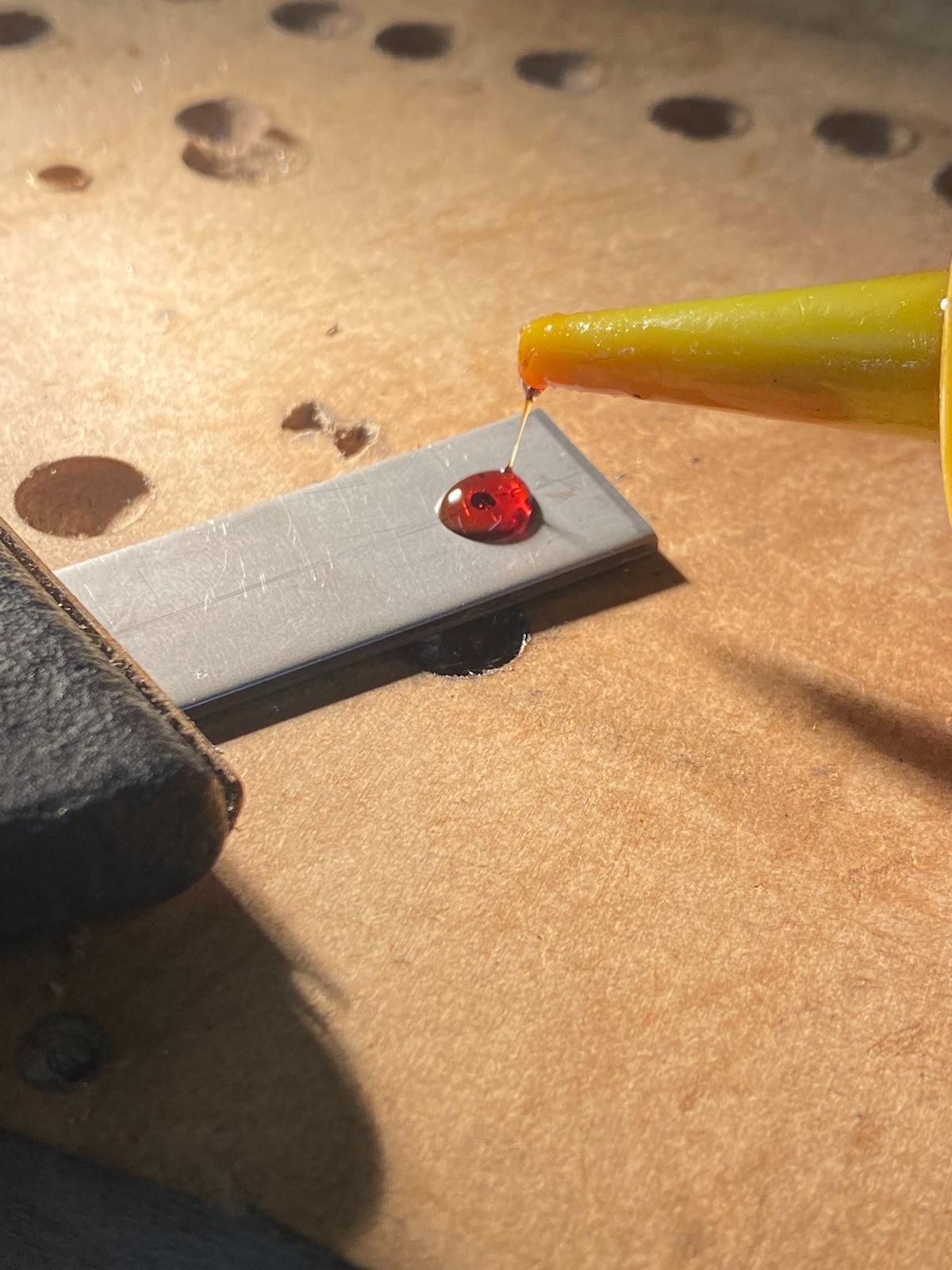
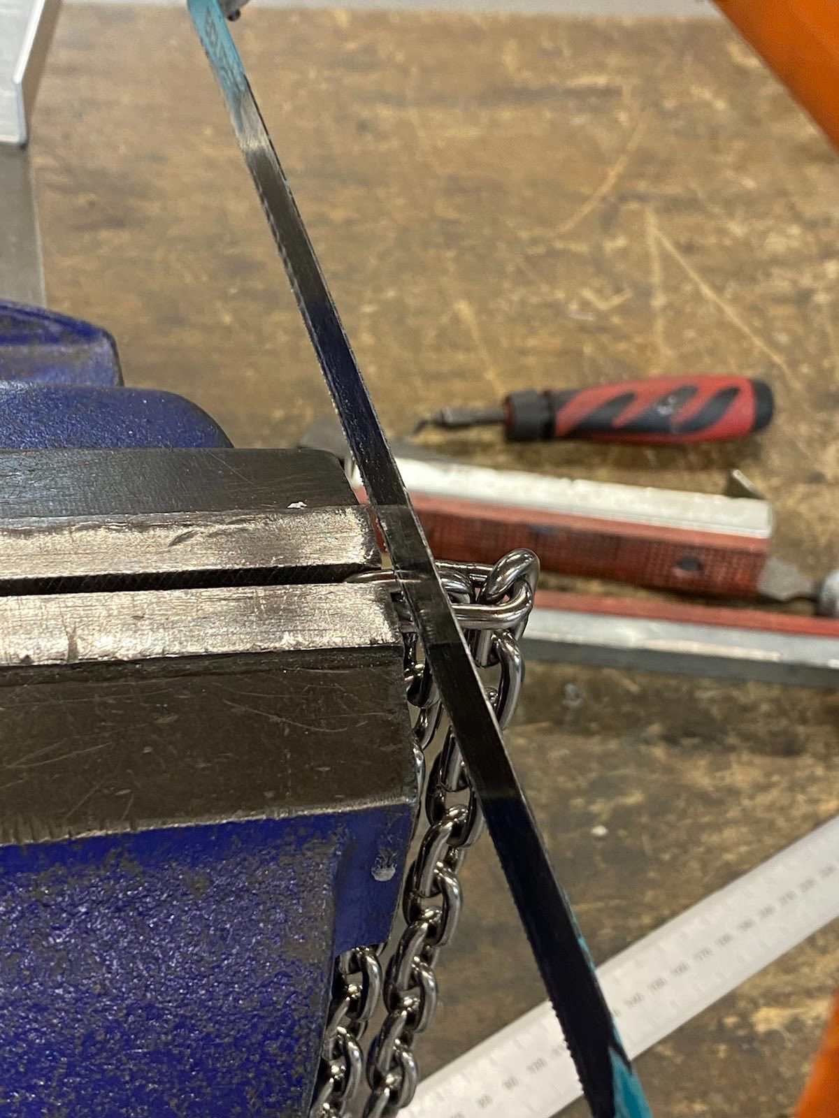
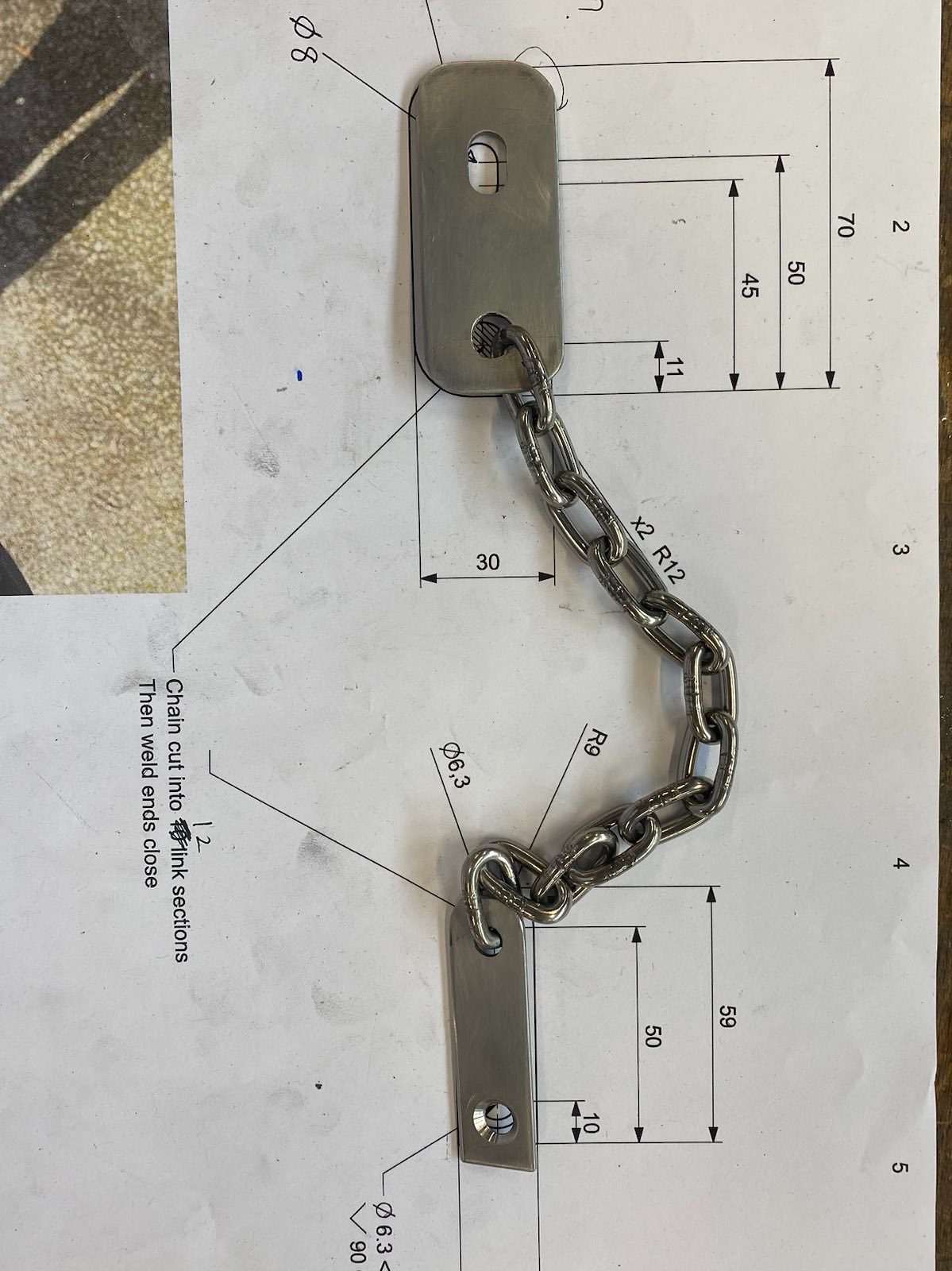
Design of stainless steel key
1

2
3
4
- Initial thoughts were using aluminium but once I started manufacturing I quickly realised how soft and easy to work with aluminium was… not an ideal material to use for a secure lock.
Conclusion & Contact
- IP34 Rating
- Weeks of battery life
- Fully programmed in Rust
testing